|
|
|
|
|
|
|
Windlass and ANCHORING System |
||||
An anchoring system was designed and installed in 2007. |
||||
|
|
|
|
|
|
|
|
|
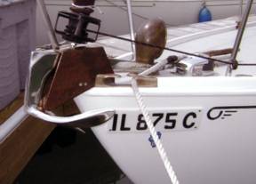
The anchor is a 22-lb stainless steel Manta
(Bruce-type). I custom-made the
bow-roller assembly from ¼” thick bronze plate and 1-1/4” thick bronze stock
to fit around the original bow casting.
Two bronze rollers are encased in the assembly. The rollers and the top plate of the
bow-roller assembly control the anchor as it is pulled into its stored
position by the windlass. The windlass is a vertical |
||
|
|
|
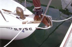
The original bronze
cowl vent brings fresh air into the anchor well and forward cabin. Any water that comes into the vent will
drain into the anchor well and out a new drain placed at the waterline. This drain has a directional check valve;
this prevents lake water from entering the anchor well when the bow punches
into big waves. |
||
|
|
|
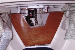
The anchor-line holding well was made from 5mm
marine plywood and mahogany edge strips.
The inside was lined with two layers of polypropylene cloth set in
West System epoxy resin (like the deck and cabin top). The front piece is varnished mahogany,
matching the interior trim. Any mud or
water that comes in on the anchor line and chain is contained and discharged
through the waterline drain mentioned above.
Nothing enters the bilge. We have 25’ of 5/16” high-tensile galvanized
chain and 270’ of 5/8” 8-plait nylon anchor line. 175' is stored in the well and the additional 120' is in reserve under the V-berth.
The windlass motor is mounted under the
deck. The short vertical drop from the
deck to the bottom of the anchor well requires a second, tailing device to
pull the line and chain into the compartment.
Without this tailing motor, the line is prone to bunching in the
windlass. The tailing device has two
gear-driven rollers. Springs permit
the distance between the rollers to be automatically adjusted to match the
size of the line. This allows the
device to smoothly tail the anchor line, as well as the sections of spliced
line and anchor chain (each with different diameters). |
||
|
|
|
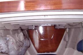
The anchor well is shown with the service
access door installed. The windlass
assembly and holding well fit within the forepeak and do not reduce the size
of the V-berth. The area on each side
of the service access door allows the cowl vent to provide fresh air to the
forward cabin. The water tank was moved from the cockpit to
underneath the V-berth. The fill
fitting is located on the deck near the bow, and the water-tank vent is above
the anchor well but inside the cabin.
This prevents deck water from entering the fresh water supply and also
prevents water-tank overflow from entering the bilge when filling the tank. |
||